POOR CONTACT BETEWEEN
BEAM FLANGE AND CONCRETE WALL---
SLOPED SHIMS
BELOW BEAM

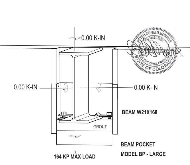
Model BP-LARGE:
- Accommodates steel beams from W16 to W27 wide
flange beams.
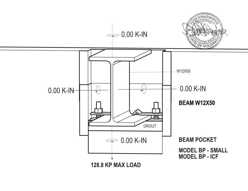
Model BP-SMALL:
- Fits steel beams from W6 to W16 wide flange
beams.
- The BP-SMALL can also be used for wood beams (with the addition of the
wood bearing Plate WP-1).
- The BP-30 is typically used on
residential and small commercial projects.
Model BP-ICF:
- For use with ICF blocks
- Same beam sizes as BP-SMALL above.
Click below to see the chart of beams which can be used with each beam
pocket.
LIST OF STEEL BEAMS THAT FIT THE BP-LARGE, BP-SMALL and
BP-ICF MODELS
LIST OF WOOD BEAMS THAT FIT THE BP-SMALL and BP-ICF
MODELS
The Beam Pocket provides support for the dead weight of the beam before leveling and grouting.
The BP-SMALL and BP-ICF models come with a 1/4 in bearing plate.
The bearing plate will support
a point load of 3 kps or 3000 pounds of
dead load - not design load - before grouting
the bearing plate.
This would equal a total unloaded dead weight of the
beam at 6000 pounds - Max for 1/4 in plate.
The BP-LARGE model comes with a 3/8 in bearing plate.
The bearing plate will support
a point load of 5.1 kps or 5100 pounds before grouting
below the bearing plate. This would equal a total unloaded dead weight
of the beam at 10,200 pounds - Max for 3/8 in plate.
If you have a point load more 5100 pounds - (the weight of the beam is more than 10,200 lbs)
give us a call
and we can supply you with a 1/2 in bearing plate which will hold 9.1 kps or 9100 pounds each end.
For a
total beam dead weight of 18,200 lbs.


The Beam Pocket directly distributes the bearing load directly into the concrete with a vertical vector.
The BP-SMALL and BP-ICF models with a 1/4 in bearing plate and
grout installed can support 124,800 lbs or
124 k.
The BP-LARGE with a 3/8 in bearing plate and
grout installed can support 164,000 lbs or 166 k.
Heavier bearing plates can be supplied with
the BP-SMALL Model and the BP-LARGE Model.
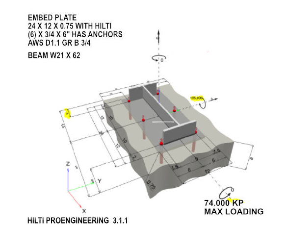
The diagram below is the loading on an embed plate from software developed by manufacturer of the embed plate studs.
Please have your structural engineer review the following:
a. The maximum point dead load on the pocket should not exceed the
limits as indicated in Section 2 above.
The design load limits should not exceed the limits in section 3 above.
b. The rebar pattern behind, to the sides and below the beam pocket should be designed by your structural
engineer.
c. The expansion and contraction requirements of the beam to be placed in the beam
pocket.
d. The type and strength of the structural grout to be placed in the
beam pocket.
e. Verify that the size of the anchor bolts meet their requirements.
The LARGE model
uses 3/4 in dia anchor bolts. The SMALL and ICF models use 1/2 in dia anchor bolts. A307/ A36 .
Click on the link below for the assembly video of the beam pocket.
ASSEMBLY OF THE BP-LARGE Beam Pocket Model
Wood and styrofoam voids generate a lot of waste with little or no possibility for recyclying. With embed plates, welding adds to carbon CO2 exhausts and VOC gas.
All the components in BP Series Beam Pocket are pre and post consumer recyclable, it can add to an overall LEED positive rating.
| LEED 4.1 CHARACTERISTICS |
BP-SERIES Beam Pocket |
WOOD VOID |
STYRO FOAM |
EMBED PLATE |
|---|---|---|---|---|
| percentage of material- pre-consumer use that is recyclable |
100% | 0% | 0% | 100% |
| percentage of material- post-consumer use that is recyclable |
100% | 0% | 0% | 100% |
| percentage of product to be disposed after installation |
3% -(1) | 100% -(2) | 100% | 3% -(3) |
| percentage of product that is released as CO2 upon disposal |
3% -(1) | 100% | 100% | 3% -(3) |
| percentage of product that is recyclable after building expiration |
100% | 0% | 0% | 100% |
| percentage of product that is subject to construction waste disposal |
3% | 100% | 100% | 3% -(3) |
| gas emission potential welding process |
0% | 0% -(2) | 0% -(2) | 100% |
| co-2 potential release during installation welding process |
0% | 0% -(2) | 0% -(2) | 100% |
| low gas emitting materials in product manufacturing |
95% | 10% -(2) | 0% -(2) | 50% - (4) |
| pollution potential from disposal |
5% | 90% | 95% | |
| VOC potential | 5% | 80% -(2) | 90% | 30% - (4) |
| notes 1- only if cardboard package is not recycled 2 - depends of wood disposal method - landfill or burning 3 - depends on shipping container or strapping 4 - depends on type of welding for stud placement |
All the parts in BP Series Beam Pocket are made in USA. All the labor to cut, bend and assemble the parts are performed in Colorado. All of the design and engineering work is performed in Colorado.
The following are examples of beam pocket problems from construction photos on the web.


